Setting
|
| |
| 1. Status |
| Display | Detail |
|---|
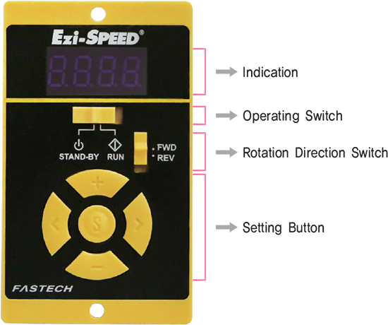
| Indication |
Display the monitor, parameter, alarm, warning. etc |
| Operating Switch |
The motor is started by setting it to the “RUN” position.
Setting it to the “STAND-BY” position stop the motor |
| Rotation Direction Switch |
Change the rotation direction of the motor with rotation direction switch. |
| Setting Button |
Changes the speed and parameters.
The value is set when the “S” button is pressed after changes are made. |
| Protective Earth Terminal |
Ground either one of the protective earth terminals. |
| Sensor Connector CN3 |
Connects to the signal connector of the motor. |
| Motor Connector CN2 |
Connects to the power connector of the motor. |
| I/O Signal Connector CN4 |
Connects with the I/O signals |
| Main Power Connector CN1 |
Connects to the main power supply and regenerative resistor. |
|
| |
| 2. Extended FunctionsEzi-SPEED can be perform various setting by operation button |
| Operating Mode | Details |
|---|
| Monitor Mode |
Speed, Actual speed, Load factor, Alarm record and reset, Warning record and reset, operating data number, I/O monitor |
| Data Mode |
Data 8 points, Operating speed, acceleration time, Deceleration time, Operating data reset |
| Parameter Mode |
The acceleration/deceleration time, The overload alarm detection time, The speed upper limit and lower limit, speed reduction ratio, speed increasing ratio, panel initial view, Alarm of “Run” condition at power on, external operation signal input, External input function, External output function, Speed attainment width, Parameter mode reset |
| NVM saving mode |
Parameter save to NVM |
|
| |
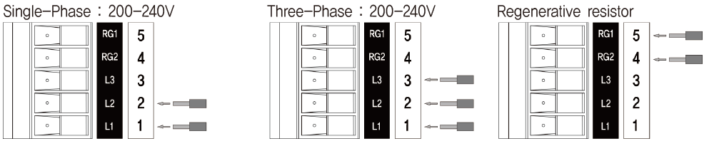
| 3. Main Power Connector(CN1) |
 |
| |
4. Applicable Lead Wire Size
AWG18 ~ 14(0.75 ~ 2.0mm2) |
| |
Operating
|
- 1. Running the motor
- Set the operation switch to the “RUN”, the motor to start rotating.
- 2. Adjust the speed
- Pressing the
 button, the speed increase by 1 r/min, button, the speed increase by 1 r/min, - Pressing the
 button, the speed decrease by 1 r/min. button, the speed decrease by 1 r/min.
- 3. Determining the speed
- - Set
Pressing the  button, the rotation speed is determined. button, the rotation speed is determined.
When the display is blinking, the rotation speed has not set.
- - Confirmation
Prevents the undesired changes in the speed,
Press the button for 5 seconds or more when STAND-BY mode when “LOCK” appears, the lock function is activated.
- 4. Stopping the motor
- Setting the operation switch to the “STAND-BY” side causes the motor to decelerate to a stop.
Setting the operation switch again to the “RUN” side causes the motor to start rotating at the set rotation speed.
- 5. Changing the rotation direction
- Change the rotation direction of the motor (gearhead) using the rotation direction switch. The rotation direction can be changed while operating. With the combination type, the rotation direction of the gearhead output shaft varies depending on the rear ratio of the gearhead.
|
|
 |
| |
|
|
Operation by I/O Signals
|
1. Operation Method
- Using the built-in power supply in the driver, the motor is operated through external signals.
- Connect Pins the I/O signal connector as in the figure of the righ.
- When operating using external signals, change the parameter setting in the “external operation signal input” to “on”. Refer to Manual.
- Using the external I/O signals, the motor can be operated 8-Speeds data. |
| |
| Pin No. |
Terminal Name |
Input/Output |
Signal Name |
Description |
| 1 |
HCOM |
Common |
- |
Input signal common : Sink Logic : +24V, Source Logic : 0V (GND) |
| 2 |
X0 |
Input |
[FWd] |
The motor rotates is FWD direction during signal “ON” |
| 3 |
X1 |
Input |
[rEv] |
The motor rotates is REV direction during signal “ON” |
| 4 |
X2 |
Input |
[P0] |
Select the operating data. |
| 5 |
X3 |
Input |
[P1] |
Select the operating data. |
| 6 |
X4 |
Input |
[A.rSt] |
Reset the alarm. |
| 7 |
LCOM |
Common |
- |
Input signal common |
| 8 |
Y0+ |
Output |
[SPd] |
For every rotation of the motor, 30 pulses are output |
| 9 |
Y0- |
Output |
| 10 |
Y1+ |
Output |
[AL.on] |
It turns off when an alarm is generated(Normally closed). |
| 11 |
Y1- |
Output |
| 12 |
Y2+ |
Output |
[MovE] |
It turns on when the motor is operated(Normally opened). |
| 13 |
Y2- |
Output |
- ※ [ ] Function in [ ] is assigned at shipment.
- ※ Can be assigned required functions to 5 input signals(X0~X4) and 3 output signals(Y0~Y2)
- Input signals : Can be used 5 functions out of FWd(CW rotation), rEv(CCW rotation),
P0(operation data 1), P1((operation data 2), P2(operation data 2), A.rst(Alarm reset), E.Err(External alarm), H-Fr( Motor activation / deactivation)
- Output signals : Can be used 3 functions out of SPd(Speed output), AL.on( Alarm output), AL.ov(Overvoltage alarm output),
- OvLd(Overload alarm output), Mov(Motor operation output), vA(Speed attainment alarm), WnG(Warning alarm)
|
| |
2. Applicable Lead Wire
SizeAWG26 ~ 20(0.14 ~ 0.5mm2) |
| |
3. Timing ChartIn
case of parameter “external operation signal input” to “on” and the rotation direction switch is set to “FWD”. |
| |
 |
· The motor rotates when either FWD input or REV input is set to “ON”.
· The motor instantaneous stop when FWD input and REV input is set to “ON” at the same time. |
| |
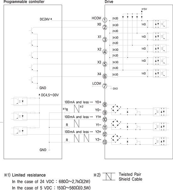
4. Connection example for I/O signals and programmable controller
This is connection example when the motor is operated using a transistor output type programmable controller.
· SINK LOGIC |
 |
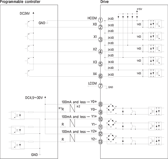 |
- ※ For the Y0, Y1 and Y2, be sure to keep the current value at 100mA or less,
If the current exceeds this value, connect the limiting resistor R.
|
| |
-
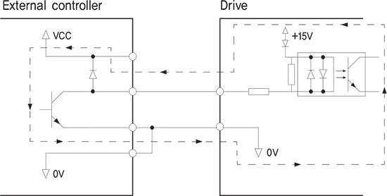
| 5. In the case of using a external controller with a built-in clamp diodeIf a external controller with a built-in clamp diode is used, a leakage path may form and cause the motor to operate even when the external controller power is off, as long as the drive power is on. Since the power capacity of the controller is different from that of the drive, the motor may operate when the external controller and drive powers ate turned on or off simultaneously. When powering down, turn off the drive power first, followed by the external controller power. When powering up, turn off the external controller power first, followed by the drive power. |
 |
| |
| |
|
|
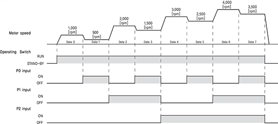 |
6. 8-Speed Operation(In the case of the “external operation signal input” parameter is set to “ON”)
① Set the operation switch to the “RUN” side.② Select the operation data number using the P0, P1 and P2 inputs.③ When either of the FWD input or REV input is turned ON, the motor will rotate.④ Switch the operation data number using the P0, P1 and P2 inputs.⑤ When the FWD input or REV input which has been turned ON is turned OFF, the motor will stop.
| Operation data No. |
P0 |
P1 |
P2 |
Rotation speed[rpm] |
|---|
| 0 |
OFF |
OFF |
OFF |
1,000 |
| 1 |
ON |
OFF |
OFF |
500 |
| 2 |
OFF |
ON |
OFF |
2,000 |
| 3 |
ON |
ON |
OFF |
1,500 |
| 4 |
OFF |
OFF |
ON |
3,000 |
| 5 |
ON |
OFF |
ON |
2,500 |
| 6 |
OFF |
ON |
ON |
4,000 |
| 7 |
ON |
ON |
ON |
3,500 |
- ※ Setting speed value is example, can change to need speed.
|
| |
Status Monitor LED
|
- 1. Monitor Mode Display
-
| Item | Display | Description |
|---|
| Setting speed display and speed adjustment[rpm] |
50 |
Display of setting motor speed |
| Actual speed[rpm] |
0 |
Monitors the actual speed of motor.
Monitors the rotation speed of gear output shaft or conveyor transfer speed when the “speed reduction ratio” parameter is set.
When the “speed increasing ratio” parameter is set, the rotation speed being increased by external mechanism is displayed. |
| Load factor(%) |
L. 0 |
Monitors the current load factor based on the rated torque being 100%.
Monitor is load factor of motor shaft. No gearhead type.
In case of gearhead mounted motor type, permissible torque is different by reduction ratio of gearhead.
Please use checking permissible torque limit of gearhead. |
| Alarm record display and record reset |
AL.rc |
Monitors the alarm record.
You can check alarm record and delate alarm record. |
| Warning record display and record reset |
Wn.rc |
Monitors the warning record.
You can check warning record and delate warning record. |
| Operation data number |
oP.d- |
Monitors the operation data No. current selected |
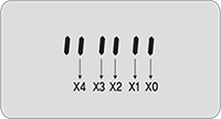
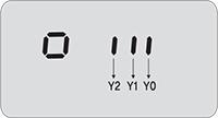
| I/O monitor |
io |
You can check the ON/OFF status of I/O signal of drive.
If the signal is ON, the corresponding LED is lit. if the signal is OFF, the LED is unlit .
Input signals
Output signals
 |
|
| |
| |
2. Protection functions and LED display
| Alarm Code | Alarm type | Cause | Remedial action | Alarm reset |
|---|
| [AL.--] |
Alarm record delate |
- |
- |
- |
| [AL.UV.] |
Under voltage |
The power supply voltage became lower than approximately 60% of the rated voltage |
1. Check the power supply voltage
2. Check the wiring of the power supply cable |
Possible |
| [AL.oV.] |
Over voltage |
1. The power supply voltage exceeded approximately 120% of the rated voltage.
2. Vertical drive(gravitational operation) was performed or a load exceeding the permissible load inertia was driven. |
1. Check the power supply voltage.
2. If this alarm occurs during operation, reduce the load or make the acceleration/deceleration time longer. |
Possible |
| [AL.oT.] |
Overheat |
The temperature inside drive exceeded the alarm detection temperature. |
Review the ambient temperature |
Possible |
| [AL.oC] |
Overcurrent |
Excessive current has flown through the drive due to ground fault. etc |
Check the wiring between the drive and motor for damage |
Possible |
| [AL.SF] |
Speed feedback |
Actual speed and set speed are different. |
1. Check the power supply voltage.
2. Check the load |
Possible |
| [AL.SS] |
Sensor error
(Hall sensor) |
The motor sensor signal line experienced an open circuit during operation or the motor signal connector came off. |
Check the wiring between the drive and motor. |
Possible |
| [AL.oS] |
Overspeed |
The rotation speed of the motor output shaft exceeded approximately 4800rpm |
1. Reduce the load
2. Review the operation pattern such as acceleration/deceleration time. |
Possible |
| [AL.oL] |
Overload |
1. A load exceeding the continuous duty region was applied to the motor for the time exceeded the value set in the “The overload alarm detection time” parameter.
2. The motor was started running under the state that the motor temperature was low. |
Possible |
| [AL.oP] |
Operation at power-on |
When the “external operation signal input” parameter was set to “OFF”, while the operation switch was set to the “RUN” side, the power was turned on again. |
Set the operation switch to the “STAND-BY” side from the “RUN” side. Next press “S” button. |
Possible |
| When the “external operation signal input” parameter was set to “ON”, while the FWD input or REV input was turned ON, the power was turned on again. |
1. Set the operation switch to the “STAND-BY” side from the “RUN” side.
2. Turn the FWD input or REV input from ON to OFF. |
| [AL.Et] |
External Error
(From external input signal) |
The motor instantaneous stop when EXT-ERROR(Stop) input. |
1. Check the EXT-ERROR input.
2. Change status from activated to deactivated. |
Possible |
|
| |
Connector
|
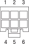
| 1. I/O Signal Connector(In/Out) |
|
3. Sensor Connector(Sensor) |
|
| No. | Function | I/O |
|---|
| 1 |
HCOM |
Common |
| 2 |
X0 |
Input |
| 3 |
X1 |
Input |
| 4 |
X2 |
Input |
| 5 |
X3 |
Input |
| 6 |
X4 |
Input |
| 7 |
LCOM |
Common |
|
| No. | Function | I/O |
|---|
| 8 |
Y0+ |
Output |
| 9 |
Y0- |
Output |
| 10 |
Y1+ |
Output |
| 11 |
Y1- |
Output |
| 12 |
Y2+ |
Output |
| 13 |
Y2- |
Output |
|
| No. | Function |
|---|
| 1 |
+5V |
| 2 |
Shield |
| 3 |
GND |
| 4 |
HALL_U |
| 5 |
HALL_V |
| 6 |
HALL_W |
|
 |
|
| |
| |
| |
| |
| |